
- About Kitsune Denshi
- Components
- Electric Items
- Equipment
- Hacks!
- Projects
For those of you interested in a multimedia audio-visual experience, there is a little overview video of the battery pack on youtube here.
If you would like to buy a ready-made replacement battery unit based on this design, N0DY Electronics is building and selling them here.
Aeons ago, the Tektronix 222 and its friends (such as the 224 and several variants thereof) were released upon the world. These are adorable little battery-powered digital scopes which may not be a match for modern portable scopes, but can still be quite useful. They are powered by an 8V sealed lead-acid battery, for which replacements stopped being manufactured a long time ago.

Sad scope. Sad owner. Bad battery!
This makes for a lot of disappointed oscilloscope owners, who can no longer use their scopes on the go. Due to form factor of the original battery, there are very few SLA batteries that can be made to fit in the scope.
Since my Tek 222 is in particularly good condition, I really wanted a battery solution that did it justice, and not just a half-arsed bodge (how unusual!). When I set out, I really wanted to achieve:
Considering as many options as I could come up with and researching what other people had done, I ended up with three broad categories of solutions that I found acceptable. These are, in order of simplicity:
As mentioned previously, SLAs that at least half fit the scope are pretty hard to come by already, so I discounted that option pretty quickly as being not future proof.
Replacing the battery with a bunch of NiMH cells is a very tempting option: A 9.6V pack will probably charge quite nicely from the scope's 8V SLA charger, and the energy density will be pretty decent as well. There are in fact records of people who have successfully done this, so it's definitely a viable option. Future availability should be great as well, so what's not to like? Well, to me it didn't feel quite right to just stick a battery pack in the scope and be done with it. It's too simple and straightforward.
That particular problem is swiftly resolved by the last option: Using new-fangled rechargeable lithium batteries. Unfortunately, neither the cell voltages nor the charging requirements lend themselves to just sticking them in the scope. Which is good, because it means I get to solve a problem - and that will be described later. Combined with the good availability of some standard sized Li-Ion cells and the good energy density, this was the option I went for in the end.
Starting out, I knew that I had to (or wanted to) build a circuit that wraps around one or more lithium cells and makes them behave like the original 8V SLA battery as far as the scope is concerned. The way I chose to achieve this is shown in the following diagram:
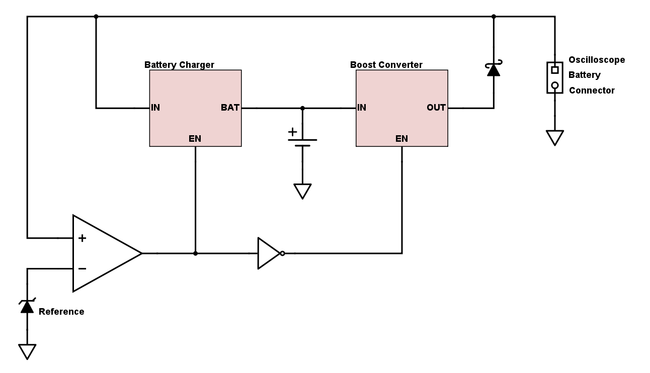
Battery pack architecture
It's really quite a simple architecture: A battery charger matched to the chosen battery technology takes care of charging the battery when the scope is plugged in. In that case, the scope outputs 9.5V on its battery connector, from which the battery charger can draw current. When the scope is unplugged, a boost converter steps up the battery voltage to approximately 8V to supply the scope just like the original battery did. A comparator senses the voltage at the scope's battery connector to detect when the scope is plugged in, and enables the battery charger or boost converter accordingly.
And that's it.

Happy scope. Happy owner. Overengineered battery!
There are a few pitfalls and trade-offs with this architecture, which needed to be considered in the circuit design.
The oscilloscope features a low-voltage cut-out at about 7.5V - if the battery voltage drops below that, the oscilloscope shuts off to prevent overdischarge of the battery. However, in this architecture a constant 8V is supplied to the scope regardless of actual battery voltage, so the scope can't take care of protecting the battery any more.
Instead, the circuit needs to ensure that the boost converter is turned off when the cells reach their discharge limit. If that does not happen, the boost converter may drain the batteries too far which may result in irreversible damage to the cell. In this design, there are two mechanisms to prevent overdischarge: First, the chosen boost converter has a 2.5V input undervoltage lockout. I would personally have liked that to be a tad higher just to be on the safe side, but it's a good to have. Then there is also a protection circuit for each cell, which will again cut out at 2.5V.
This one is a right mess. First, let's start with the number of cells:
The favoured cylindrical cells have relatively low capacity compared to e.g. prismatic cells, so in order to reach the target capacity, more than once cell is required. This immediately results in the question of whether to put them in series or parallel, and there are pros and cons for each:
Parallel cells are the simplest solution. As long as the cells are matched, they simple behave like one big cell, which means that as far as the charger is concerned, no special precautions need to be taken. Furthermore, not all cells need to be fitted, which gives a bit of extra flexibility.
Series cells are a fair bit more complex: A multi-cell charger is required, as well as a cell balancing circuit. In addition, all cells need to be present when they are placed in series. With the general idea being to be as flexible as possible when it comes to cells, a series arrangement is not ideal from that point.
However, connecting cells in series increases to input voltage of the converter, potentially to over the required 8V for three in series. This would be desirable for the following reason: Internally, the oscilloscope has a bunch of switch-mode converters, some of which draw quite substantial current on power-up. If the battery voltage is below the required 8V, a multiple of that current is drawn from the batteries. In addition, if a boost converter is used, that by itself will have a fair inrush current, so on power-on the current that needs to be supplied by the batteries and the converter may be substantial.
On the other hand, if the battery voltage exceeds 8V, the inrush current drawn from the batteries is a fraction of that drawn by the scope. Furthermore, buck converters are lighter themselves in terms of inrush current, so the overall situation would be better.
Trading off the charger complexity against the converter topology, I decided to stick with parallel cells. The simplicity of managing and charging a single cell in my opinion outweighs keeping the inrush currents low. Li-Ion cells will be quite happy to provide large peak currents anyway, and massively oversizing storage capacitors will help to keep down the peak current that the boost converter needs to supply.
The choice of cells was largely based on mechanical constraints. The scope can just about accommodate a holder for 3 18650 cells, which are among the most common cylindrical Li-Ion cells. This makes them cheap and hopefully easily available in the future, which really is the main requirement I have. Furthermore even lower capacity types will easily match the capacity of the original SLA battery, which is another important requirement taken care of.
In order to behave like the expected lead acid battery, the circuit must provide 8V all the time - even when the oscilloscope is turned off. It is therefore important that the quiescent power consumption is kept low so that the battery pack can stay in the scope for a reasonable amount of time without having to recharge. However, it turns out that it may not be necessary to squeeze out every last microamp, because when powered off, the scope itself will draw a healthy 300µA, which translates into >600µA from the battery.
Low power consumption was mainly achieved by component choice. This covers both basic quiescent current figures, as well as operating modes. For example, the LTC1872 boost converter only operates in short burst at very light loads, which improves overall efficiency compared to parts that may have lower quiescent current, but operate continuously.
Some of the information in this section is scattered throughout the article, so I thought it would be good to pull it together into one place.
The oscilloscope has a nominal battery voltage of 8V, and will cut out below approximately 7.5V. When plugged in, it applies approximately 9.5V to the battery terminals.
Powered off, it draws approximately 300µA at 8V. Powered on, the maximum current draw (highest intensity, both channels sampling fastest) was below 700mA. Whilst powered on, the scope will supply a charge current of about 500mA (exceeding this will shut down the scope). Powered off, it can provide a charge current of >1A.
The boost converter was designed to comfortably supply >800mA at 8V. The charger was designed to have a maximum charge current of around 600mA (around 300mA drawn from the scope) in order to not exceed the maximum charge current provided when the scope is powered on. It is a bit annoying that I can't take advantage of the full charge current when the scope is turned off and plugged in - maybe I'll think of something for the next version.
Of course, we don't want our oscilloscope to turn into an incendiary charge. For that reason, each cell has its own cell protection IC, which should be enough to prevent things from going horribly wrong. In particular, it will disconnect cells when they are being overcharged, which is probably the single most important safety measure.
Additionally, the charger IC has provisions for a cell temperature sensor, and this has been routed out on the board. However, it is only designed to handle one thermistor, and I don't think I can get the trip points right with three thermistors. Hence, there are no thermistors for overtemperature cut-off fitted on my board, but they can be added.
In the end, the circuit I designed was more or less the above block diagram implemented with fairly straightforward standard components:
I think most of the interesting aspects of the design have been covered already, but if you have any particular question please contact me (about page).
You can download the design files from here:
The above files are for Revision 1 of the board, which has been built a number of times and proved to be robust.

The business end (electronics-wise)

The other end of the business end.
This part of the design took me the longest to arrive at a satisfactory solution. I didn't just want to have a board dangling in the battery compartment, but something that looked decent.
Since the battery holder I picked was a little bit too slim to be held securely but the rubber inserts in the scope, I had to have some means of making it a few millimetres wider, and the simplest solution for that was a piece of acrylic. But when I already have one piece of acrylic, I might as well have some more to stand off the back of the board. And when I've got that, I might as well enclose the electronics in some more acrylic to make it look like a real case.
I ended up laser cutting little bits from matte black 3mm acrylic and building a case from that. At first I used smoked dark grey acrylic, but that didn't look anywhere near as good as the matte black - in my opinion. This also allowed me to have a neat front panel with status lights. The LEDs are mounted on the board, and I again used laser cut acrylic to make my own light pipes - which worked surprisingly well!
The drawings for the acrylic parts will be uploaded here in the next few days. But beware, there was quite a bit of trial and error involved to get the dimensions work out just right on the laser cutter, so the parts might come out differently on your end.

Stand-off ribs.

Home-made light pipes. Mmmmhhh… hot glue!

The 80's called, they want their industrial design back.
After initial testing, everything seemed to work just fine with the board outputting its 8V. However, when a decent load of a few hundred milliamps was attached, it started to switch rapidly between charge and supply modes.
I was suspecting additional noise on the output of the boost converter, but couldn't quite track down where it was causing mayhem. My initial idea was that it must be at the input of the comparator, but that wasn't the case. After a bit more measuring around, it turned out that the voltage reference of the comparator dropped from 0.4V to about 0.3V when the supply is more noisy. That's a lot!
The datasheet does mention that the reference is sensitive to noise, but I didn't expect it to have that kind of effect. Adding a 4.7μF decoupling cap on the comparator in parallel to the existing 100nF solved that issue. If I were to re-spin the board, I'd probably add an RC filter on the supply line, just to be on the safe side.