
- About Kitsune Denshi
- Components
- Electric Items
- Equipment
- Hacks!
- Projects
This is an old revision of the document!

Lovely LEDs in most of the colours of the rainbow.
Who doesn't like advent calendars? Even if one doesn't celebrate Christmas or tries to shield oneself from the festive season as much as possible, there is something special about advent calendars. I think it's the counting down towards an arbitrary goal, a new surprise (maybe chocolate!) every day and of course the objectification of anticipation. A bit like obsessively following the tracking information on a package, when you think about it.
At some point in late November 2015 a retina-searing LED arms race (sparked by some harmless albeit woefully underpowered Christmas decorations) was well under way in the office. This almost naturally led on to building an LED advent calendar, so that the combined joys of advent calendars and LEDs could be shared with my colleagues.
Unfortunately, as mentioned above, December was already looming on the horizon, so a decision on exactly what kind of LED advent calendar should be constructed and procurement of components had to proceed with the greatest haste. The following is a day-by-day account on the development of the luminous advent calendar:
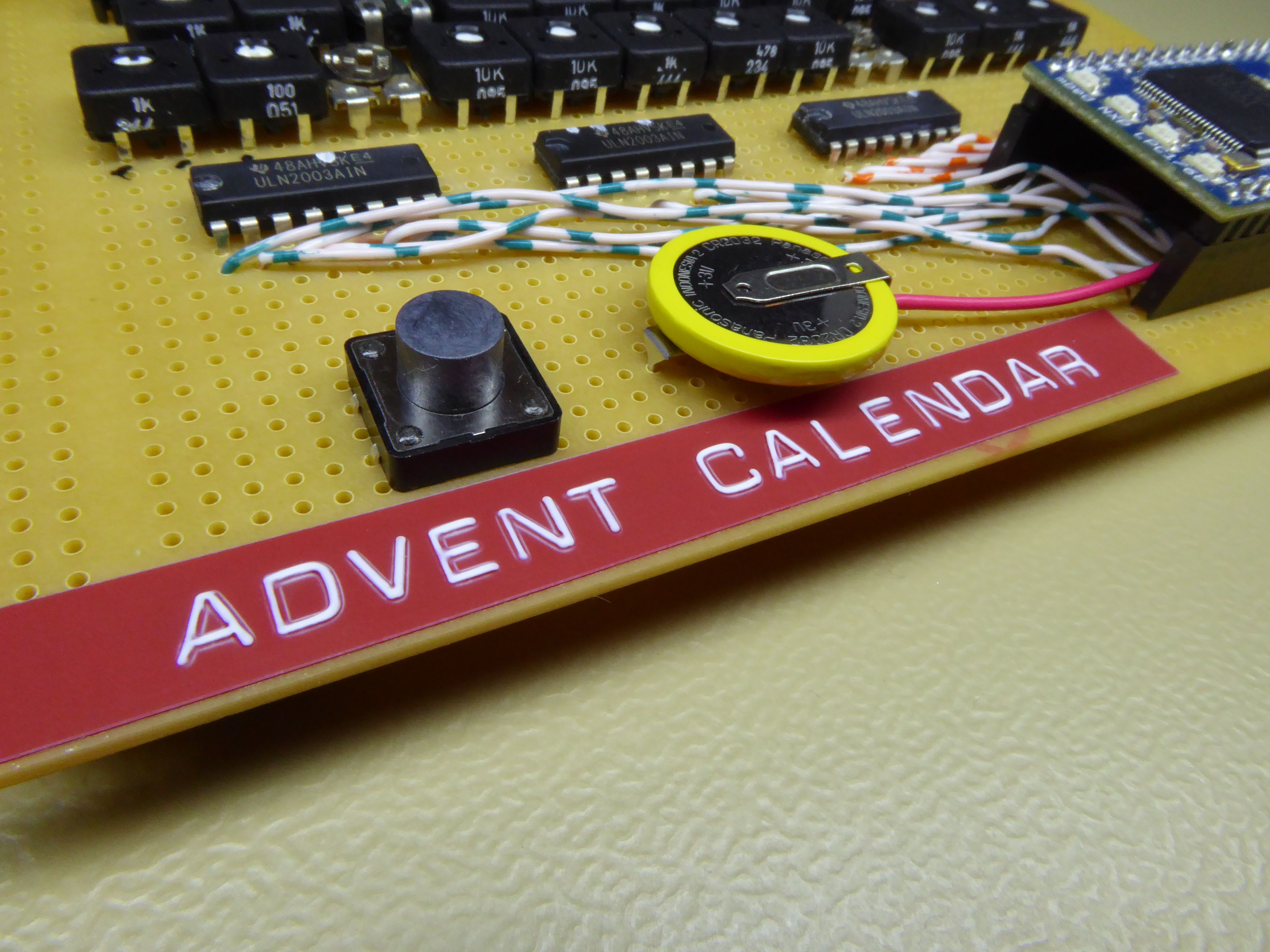
No hacky project would be complete without the application of a Dymo label.
After carefully thinking about what it is that makes advent calendars exciting for me (doing something, getting a surprise, building up towards something), I came up with the following concept that consists of:
The calendar starts off with all LEDs turned off. When the button is pressed, a random LED turns on (and remains on). Each additional push of the button turns on an additional LED, until all 24 are lit after 24 days.
As always, there are a few complications:
The circuit used is embarrassingly simple: Each LED is powered from the USB supply, driven by a ULN2003, and has its current limited by a trimmpot. There is one GPIO pin for each LED, so no fancy multiplexing or anything clever.

LED driver schematic. There are 24 of these.
There are a few reasons why this rather inelegant and simple driving method was chosen:
The resistor values for the trimmers were calculated beforehand to get a rough idea of the values required to equalise the perceived brightness of all LEDs. However, as one would imagine, there was quite a bit of tweaking involved in the end to get everything looking just right - and unfortunately I ran out of trimmers of the same style and had to resort to a few even crustier ones from my box.
Apart from that, literally the only other components on the board are a pushbutton switch with a pull-up resistor and a CR2032 for the battery-backed RTC of the mbed.

Boring.

Doesn't look as good with bright light coming from above.
Coming soon.