
Table of Contents
Keithley 2231A-30-3
Introduction
The Keithley 2231A-30-3 a triple-channel bench power supply. It comes with two 0-30V, 0-3A channels, and one 0-5V, 0-3A channel.
In the overall scheme of things, this unit sits on the lower end of the price spectrum for big-name brand feature-packed power supplies. Unfortunately, it does show that the unit was built down to a price.
Quick Look Inside
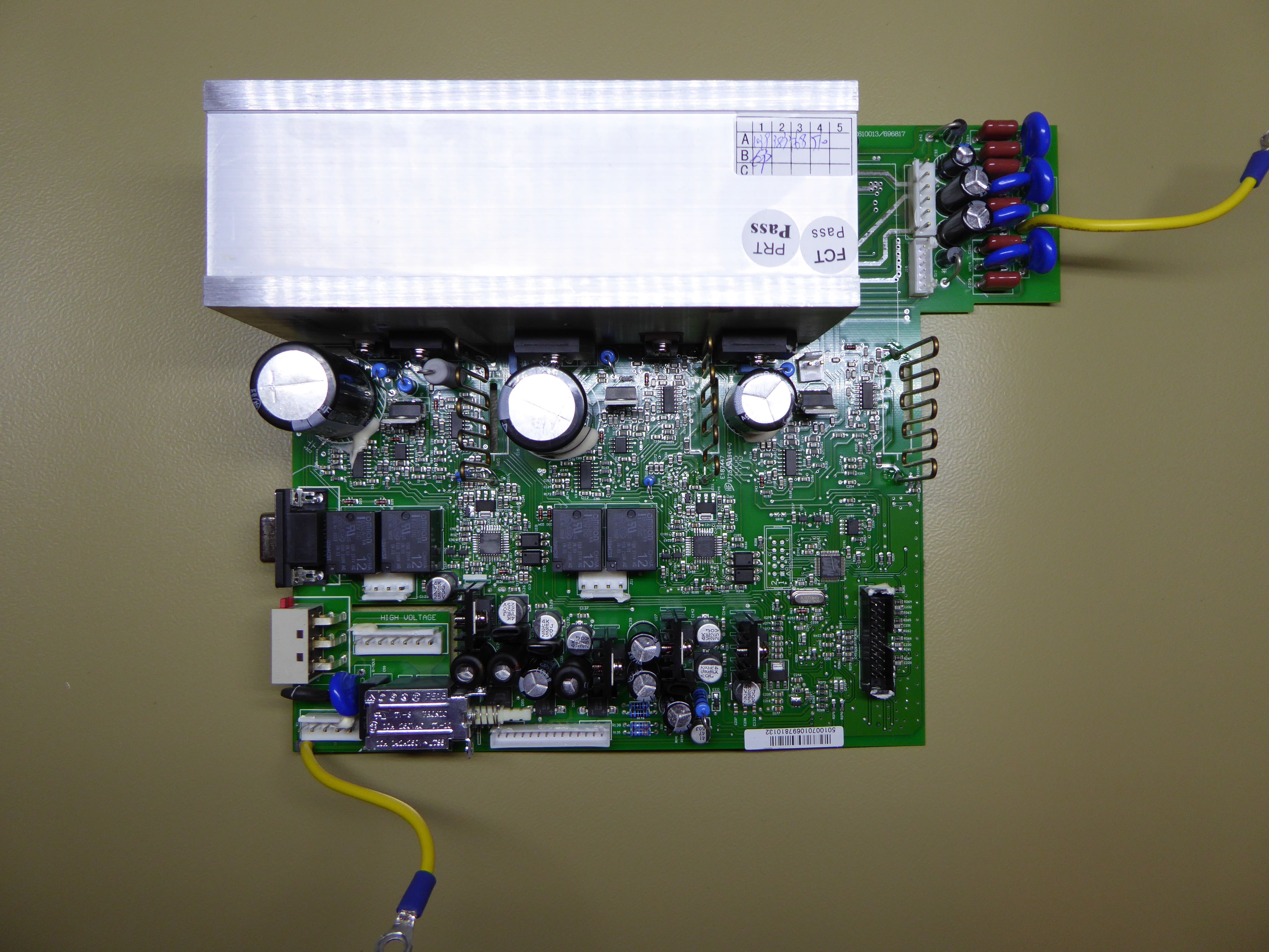
Main board (top).

Main board (bottom).

Not. Trying. Hard. Enough!

Mmmmh, Lelon. Just the finest.
Set-Point Generation
Assumption is the mother of all fuck-ups.
Various Sources
A lot of the original description in this section was based on an incorrect assessment of the set-point generation circuit, which was mainly due to my assumption that a measured 3.3V voltage would have come from the main 3.3V regulator. In the interest of clarity, I have removed the blatantly incorrect descriptions from this sections, whilst trying to preserve as much of the original as possible. Feel free to dive into the page history to see what my original idea was.
Whilst doing a teardown video of the power supply, I discovered that the way the set points for voltage and current are generated are not quite what I had expected. The variable set point voltage is simply generated through a PWM output from a microcontroller, which goes through a two-stage RC filter and then straight into the control electronics:
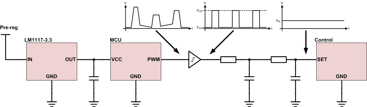
Set point generation.
The PWM comes directly from the microcontroller, and is buffered by single-gate logic IC (74LVC1G14, 74LVC1G34 or similar). Whilst a small part of the function of this buffer may be to clean up the waveform from the microcontroller (as suggested in the figure), it is really there to translate the PWM to much better-defined voltage levels. The buffer is powered from a precision reference (REF3025 for channels 1 and 2, and REF3033 for channel 3), which means that its output voltage levels, and hence the generated DC signal after the filter, are much more accurate. If the PWM signal were taken directly from the microcontroller (and its poorly specified supply rail), the instrument would be unlikely to achieve its specifications.
Whilst I would have expected to see a dedicated DAC chip, there is nothing wrong with this approach as such. In fact, using a PWM is probably one of the easiest ways to get a high resolution analogue signal from a microcontroller. Being digitally generated, the accuracy of the duty cycle is also extremely high, and the limiting factor for accuracy is the accuracy of the voltage levels of the PWM signal. After the buffers, these levels are derived from a precision reference, and there should likewise be no issues with accuracy there.
However, do have one tiny little niggle about using a buffer powered from the reference voltage: Unlike ideal logic gates favoured by academics, the power supply contains real components. In a real logic gate, the output voltage levels aren't 0V and the supply voltage, but voltages close to the rails, $V_{OL}$ and $V_{OH}$.
As such, the equation for the output voltage after filtering is:
$V_{flt} = V_{OH} \cdot DC + V_{OL} \cdot (1 - DC)$
where $DC$ is the duty cycle of the PWM waveform. $V_{OL}$ and $V_{OH}$ vary between individual devices, and on the same device depend on the load current, temperature, and many other parameters. Which means that, theoretically, they could mess up the nice reference voltage.
In practice, this will be of very little concern in this instrument, because the load is constant and hence can be taken care of by calibration. Furthermore, because the load resistance is relatively high compared to the output resistance of the buffer, variation in the output resistance due to temperature is likely minute.
One other slight niggle with this whole system is that the PWM frequency is fairly low (1kHz), so I'm not entirely convinced that the RC filter will be doing a great job at making a very clean DC signal. However, I think this might actually be a non-issue, because the control loop for voltage and current is probably slow enough (in the scheme of things) to filter out any remaining components from the switching frequency.
Overall, whilst I think it is a bit unusual to find this approach in an instrument, it works and the power supply meets its specifications very well. Keithley have clearly carefully considered all the options (and did not outright go for the highest-precision DAC), and managed to find a low-cost solution that performs really quite well.
Fan Replacement
The combination of the instrument's compact form factor and the laws of physics result in potentially quite a bit of heat that needs to be removed from the inside of the case. Keithley have chosen a large heatsink with all the power semiconductors mounted to it, and a fan that blows air through the heatsink to the outside.
The good news is, the fan is temperature controlled. The bad news is, it's a noisy little bastard!

WHIRRRRRRRRR!
It wouldn't be so bad if the fan only came on under high loads, but it will start on low speed even when the power supply is idle. Unfortunately, those are usually times when I'm sitting there poring over a circuit, and the last thing I want is a whiny fan in the background.
One quick delivery from a mail-order electronics shop later, and the power supply now sports a Papst 612NGLE. Unfortunately, the reduction in noise wasn't as much as I had hoped. First, there is a fair amount of noise coming from the airflow through the heatsink itself - which I can't really do much about. Second, the mounting of the fan to the heatsink and the construction of the chassis is really good for propagating vibrations. So I will continue investigating, and probably fit some sort of anti-vibration mount.

whirrrrrrrrr