
- About Kitsune Denshi
- Components
- Electric Items
- Equipment
- Hacks!
- Projects
This is an old revision of the document!
The panel meter in my 332B was broken and unfortunately not repairable. API very helpfully quoted $495.00 for a replacement model 302 meter. Thanks, but no thanks. After a month or so one came up for a reasonable price on ebay - not a perfect match, however, since it was a -100μA - 0 - +100μA meter, whereas I needed 0 - 100μA. But close enough.
The meter itself could me modified easily. All that was needed was to adjust the pre-tension of the return spring to move the zero reading to the left. One slight annoyance was that in this position, the zero adjustment needed to offset by half an indentation. This was swiftly accomplished by careful application of super glue.
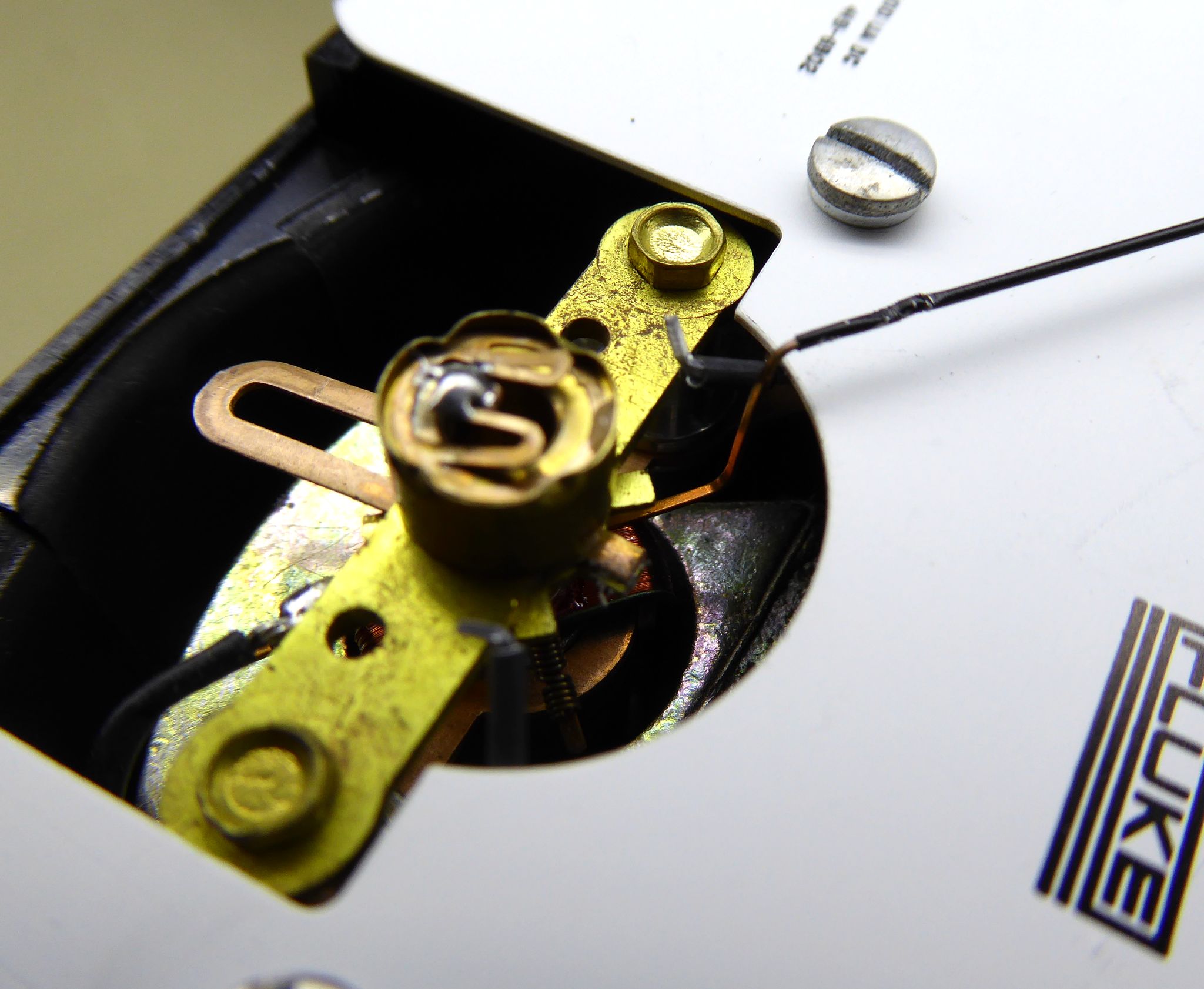
Mechanical meter mod.
Now that the meter is effectively 0 - 200μA, the meter drive circuitry in the 332B needs modification as well.

Schematic of the meter drive circuitry.
The potentiometer R5 is used to adjust the full-scale deflection of the meter. But unfortunately, not in a wide enough range. The obvious solution would be to also decrease the value of R4 to get more current through the meter. But before we do that, some maths. Consider the following simplified circuit, where R4, R5 and the meter are combined into Rm and the divider resistors (R1-R2, R3-R4, R5-R7) and R3 are combined into RD.

Simplified meter circuit.
The current (Im) through the meter for a given output voltage V is: $I_m = \frac{V \cdot R_6}{R_D \cdot R_m + R_D \cdot R_6 + R_m \cdot R_6}$
From this, it can be calculated that It is not possible to find values for R6 and Rm that will allow 200μA through the meter for a full-scale reading. The closest that could be achieved would be 190μA with R6 = ∞ and Rm = 330Ω (the meter DC resistance). Hence, the only solution is to modify the divider resistors.
Assuming a reasonable Rm (4.7kΩ) the above equation can be solved for three new divider resistors RD1, RD2 and RD3, corresponding to the 10V, 100V and 1000V range:
This can be achieved by the following modifications:
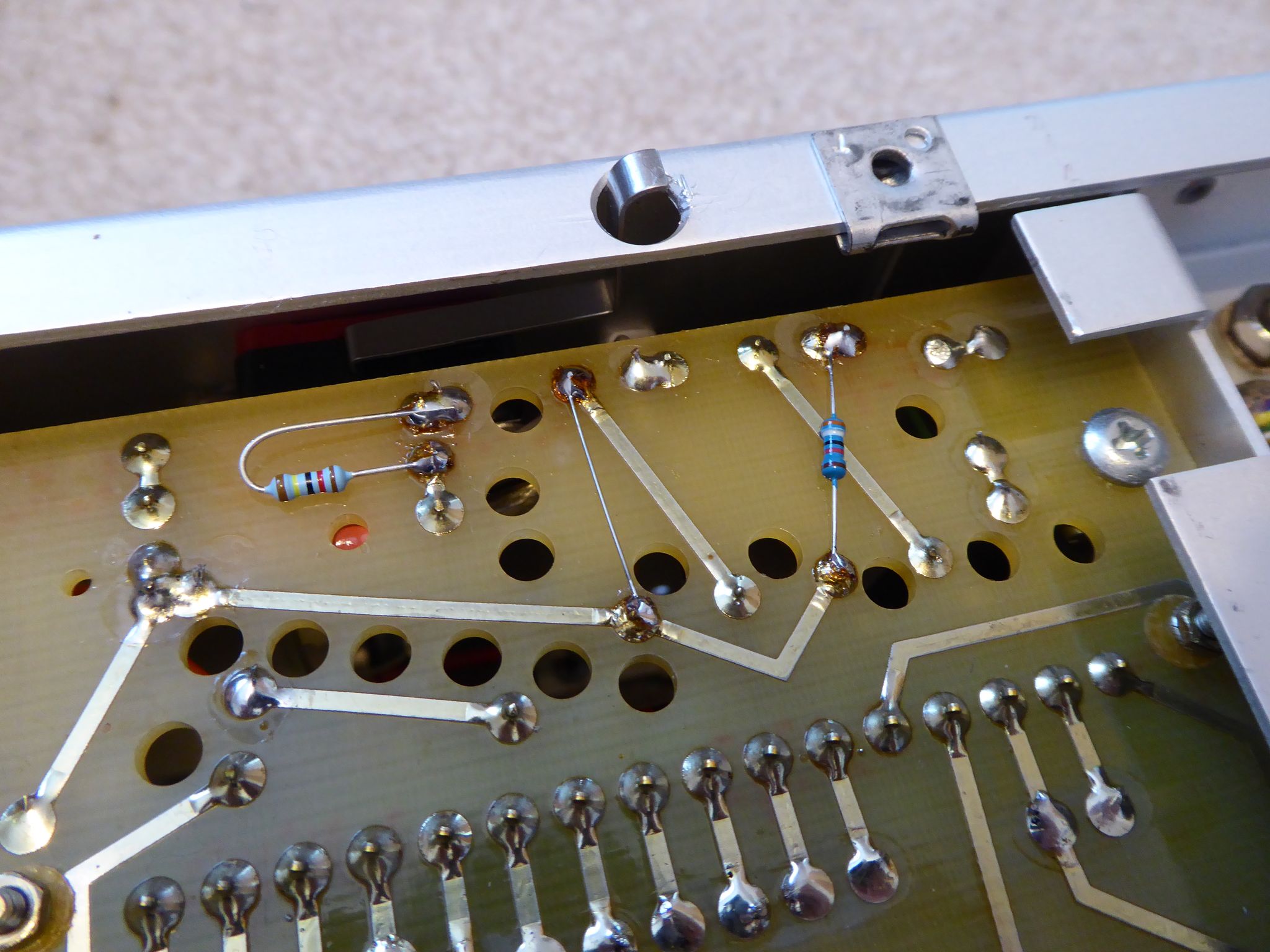
Modified voltage divider (on backplane).
As with any such modifications, the ratings of the resistors must be taken into consideration. In this case, normal 0.25W metal film resistors were used - that's fine in terms of power, but slightly dodgy in terms of voltage for the 1.2MΩ resistor. This might be a good excuse to get those nice kV-rated Megaohm resistors I've always been too cheap for.
These modifications worked as expected and the full-scale reading of the meter can still be fine-tuned through R5.
Similarly, the divider for the current range must also be modified. However, this task is much simpler than the voltage divider, as there is only a single 50mA current range. Add a 2.7kΩ resistor in parallel to R1 and 50mA on the output will translate into 200μA on the meter.
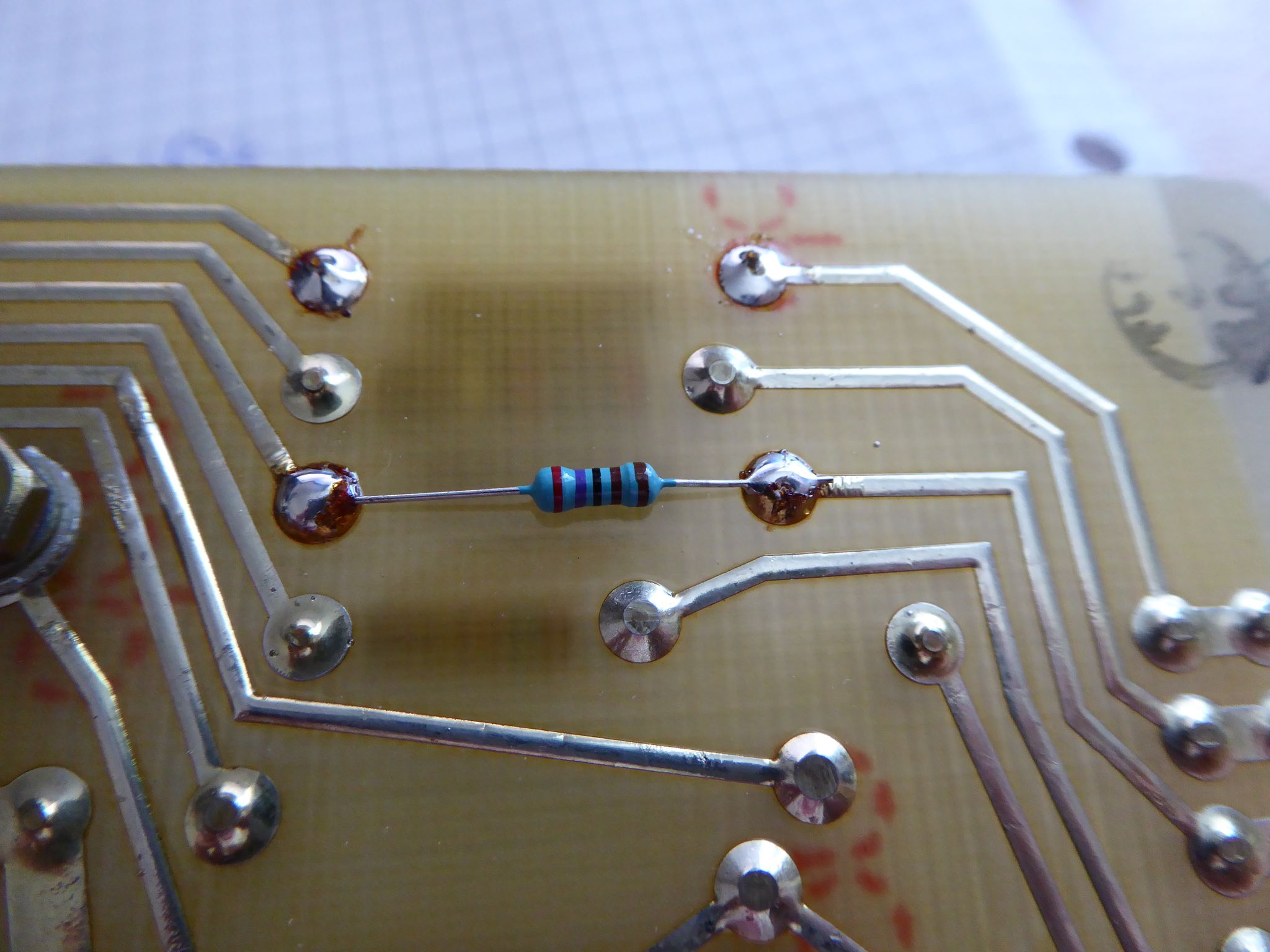
Modified current divider.
Again, everything worked perfectly after adjusting the full-scale reading with R2.